In this Unity tutorial, we’ll be creating a Wireframe shader in Unity with Unity’s ShaderLab code. This tutorial is suited to someone who is familiar with the Unity Editor interface and comfortable with code.
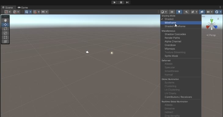
A wireframe shader can be used in many different situations including prototyping, creating a cool AR or cybernetic feel for an object in a game, creating a net-like material, or just helping you see the wireframe shapes of the objects you’re working with (although, since Unity has this as one of the Shading Mode options within the Scene window, I’d suggest you just use that instead of building a shader to see object shapes).
Project setup
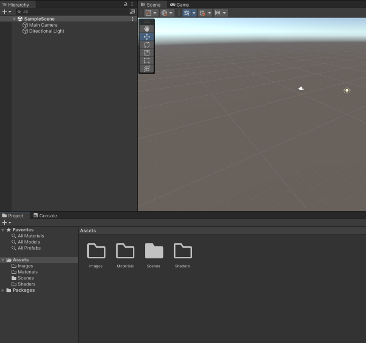
Great! Now that we have our wireframe texture created, we can go ahead and create the project that we’ll be working in and create our shader. To do this, create a new 3D project in the Unity Hub and wait for Unity to complete the project creation.
I then created three folders, namely a Materials folder, a Shaders folder, and an Images folder.
Creating the shader
Let’s set up our shader by creating a material for it. In the Shaders folder, right-click the empty space, select Create from the context menu, and then select Shader and Unlit Shader.
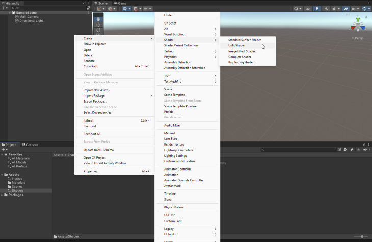
Let’s name it according to our project’s naming convention, which in my projects is Type_Description_SubDescriptionIfNeeded, and call it Shader_Unlit_WireframShader.
Double-click your newly created shader and it should open up in the IDE assigned to your Unity Editor. (I will be editing the default shader so that you can follow along through each step of the way.)
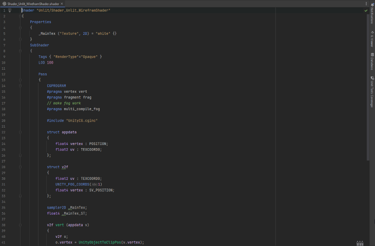
Let’s change the Queue that we want this to execute to Transparent and set the Blend to SrcAlpha OneMinusSrcAlpha:
Shader "Unlit/Shader_Unlit_WireframShader"
{
    Properties
    {
        _MainTex ("Texture", 2D) = "white" {}
    }
    SubShader
    {
        **Tags { "RenderType"="Opaque" "Queue"="Transparent" }**
        LOD 100
                **Blend SrcAlpha OneMinusSrcAlpha**

        Pass
        {
            CGPROGRAM
            #pragma vertex vert
            #pragma fragment frag
            // make fog work
            #pragma multi_compile_fog

            #include "UnityCG.cginc"

            struct appdata
            {
                float4 vertex : POSITION;
                float2 uv : TEXCOORD0;
            };

            struct v2f
            {
                float2 uv : TEXCOORD0;
                UNITY_FOG_COORDS(1)
                float4 vertex : SV_POSITION;
            };

            sampler2D _MainTex;
            float4 _MainTex_ST;

            v2f vert (appdata v)
            {
                v2f o;
                o.vertex = UnityObjectToClipPos(v.vertex);
                o.uv = TRANSFORM_TEX(v.uv, _MainTex);
                UNITY_TRANSFER_FOG(o,o.vertex);
                return o;
            }

            fixed4 frag (v2f i) : SV_Target
            {
                // sample the texture
                fixed4 col = tex2D(_MainTex, i.uv);
                // apply fog
                UNITY_APPLY_FOG(i.fogCoord, col);
                return col;
            }
            ENDCG
        }
    }
},
In our properties, let’s add variables for our wireframe’s front, back, color, and width:
Shader "Unlit/Shader_Unlit_WireframShader"
{
    Properties
    {
        _MainTex ("Texture", 2D) = "white" {}
                **_WireframeFrontColour("Wireframe front colour", color) = (1.0, 1.0, 1.0, 1.0)
        _WireframeBackColour("Wirefram back colour", color) = (0.5, 0.5, 0.5, 1.0)
        _WireframeWidth("Wireframe Width", float) = 0.05**
    }
    SubShader
    {
        **Tags { "RenderType"="Opaque" "Queue"="Transparent" }**
        LOD 100
                **Blend SrcAlpha OneMinusSrcAlpha**

        Pass
        {
            CGPROGRAM
            #pragma vertex vert
            #pragma fragment frag
            // make fog work
            #pragma multi_compile_fog

            #include "UnityCG.cginc"

            struct appdata
            {
                float4 vertex : POSITION;
                float2 uv : TEXCOORD0;
            };

            struct v2f
            {
                float2 uv : TEXCOORD0;
                UNITY_FOG_COORDS(1)
                float4 vertex : SV_POSITION;
            };

            sampler2D _MainTex;
            float4 _MainTex_ST;

            v2f vert (appdata v)
            {
                v2f o;
                o.vertex = UnityObjectToClipPos(v.vertex);
                o.uv = TRANSFORM_TEX(v.uv, _MainTex);
                UNITY_TRANSFER_FOG(o,o.vertex);
                return o;
            }

            fixed4 frag (v2f i) : SV_Target
            {
                // sample the texture
                fixed4 col = tex2D(_MainTex, i.uv);
                // apply fog
                UNITY_APPLY_FOG(i.fogCoord, col);
                return col;
            }
            ENDCG
        }
    }
},
Creating the shader’s passes
We have to create two passes for this shader. In the first, we’ll create the pass for the forward-facing triangles. However, since the process of creating the back-facing triangles is almost identical to the process of creating the front-facing triangles, we’ll create the front-facing triangles and I’ll show you the code for the back-facing triangles as well.
We can start by focusing on the forward-facing triangles by using Cull Back to remove the back-facing triangles:
Shader "Unlit/Shader_Unlit_WireframShader"
{
    Properties
    {
        _MainTex ("Texture", 2D) = "white" {}
                **_WireframeFrontColour("Wireframe front colour", color) = (1.0, 1.0, 1.0, 1.0)
        _WireframeBackColour("Wirefram back colour", color) = (0.5, 0.5, 0.5, 1.0)
        _WireframeWidth("Wireframe Width", float) = 0.05**
    }
    SubShader
    {
        **Tags { "RenderType"="Opaque" "Queue"="Transparent" }**
        LOD 100
                **Blend SrcAlpha OneMinusSrcAlpha**

        Pass
        {
                        **Cull Back**
            CGPROGRAM
            #pragma vertex vert
            #pragma fragment frag
            // make fog work
            #pragma multi_compile_fog

            #include "UnityCG.cginc"

            struct appdata
            {
                float4 vertex : POSITION;
                float2 uv : TEXCOORD0;
            };

            struct v2f
            {
                float2 uv : TEXCOORD0;
                UNITY_FOG_COORDS(1)
                float4 vertex : SV_POSITION;
            };

            sampler2D _MainTex;
            float4 _MainTex_ST;

            v2f vert (appdata v)
            {
                v2f o;
                o.vertex = UnityObjectToClipPos(v.vertex);
                o.uv = TRANSFORM_TEX(v.uv, _MainTex);
                UNITY_TRANSFER_FOG(o,o.vertex);
                return o;
            }

            fixed4 frag (v2f i) : SV_Target
            {
                // sample the texture
                fixed4 col = tex2D(_MainTex, i.uv);
                // apply fog
                UNITY_APPLY_FOG(i.fogCoord, col);
                return col;
            }
            ENDCG
        }
    }
},
Great. The #pragma lines define each of the functions that we’re going to use. The fragment shader is where we will take care of the color of our triangles, but we don’t need to alter the vertex function.
We do, however, need to add a custom geometry function because we want to add coordinates to each of our triangles:
Shader "Unlit/Shader_Unlit_WireframShader"
{
    Properties
    {
        _MainTex ("Texture", 2D) = "white" {}
                **_WireframeFrontColour("Wireframe front colour", color) = (1.0, 1.0, 1.0, 1.0)
        _WireframeBackColour("Wirefram back colour", color) = (0.5, 0.5, 0.5, 1.0)
        _WireframeWidth("Wireframe Width", float) = 0.05**
    }
    SubShader
    {
        **Tags { "RenderType"="Opaque" "Queue"="Transparent" }**
        LOD 100
                **Blend SrcAlpha OneMinusSrcAlpha**

        Pass
        {
                        **Cull Back**
            CGPROGRAM
            #pragma vertex vert
            #pragma fragment frag
                        **#pragma geometry geom**
            // make fog work
            #pragma multi_compile_fog

            #include "UnityCG.cginc"

            struct appdata
            {
                float4 vertex : POSITION;
                float2 uv : TEXCOORD0;
            };

            struct v2f
            {
                float2 uv : TEXCOORD0;
                UNITY_FOG_COORDS(1)
                float4 vertex : SV_POSITION;
            };

            sampler2D _MainTex;
            float4 _MainTex_ST;

            v2f vert (appdata v)
            {
                v2f o;
                o.vertex = UnityObjectToClipPos(v.vertex);
                o.uv = TRANSFORM_TEX(v.uv, _MainTex);
                UNITY_TRANSFER_FOG(o,o.vertex);
                return o;
            }

            fixed4 frag (v2f i) : SV_Target
            {
                // sample the texture
                fixed4 col = tex2D(_MainTex, i.uv);
                // apply fog
                UNITY_APPLY_FOG(i.fogCoord, col);
                return col;
            }
            ENDCG
        }
    }
},
Now, let’s create a g2f (geometry) struct to house the barycentric coordinates of the triangles. We’ll need to add the position as well an extra float called barycentric that we’ll assign to TEXCOORD0:
Shader "Unlit/Shader_Unlit_WireframShader"
{
    Properties
    {
        _MainTex ("Texture", 2D) = "white" {}
        _WireframeFrontColour("Wireframe front colour", color) = (1.0, 1.0, 1.0, 1.0)
        _WireframeBackColour("Wirefram back colour", color) = (0.5, 0.5, 0.5, 1.0)
        _WireframeWidth("Wireframe Width", float) = 0.05
    }
    SubShader
    {
        Tags { "RenderType"="Opaque" "Queue"="Transparent" }
        LOD 100
        Blend SrcAlpha OneMinusSrcAlpha

        Pass
        {
            Cull Back
            CGPROGRAM
            #pragma vertex vert
            #pragma fragment frag
            #pragma geometry geom
            // make fog work
            #pragma multi_compile_fog

            #include "UnityCG.cginc"

            struct appdata
            {
                float4 vertex : POSITION;
                float2 uv : TEXCOORD0;
            };

            struct v2f
            {
                float2 uv : TEXCOORD0;
                UNITY_FOG_COORDS(1)
                float4 vertex : SV_POSITION;
            };

                        **struct g2f
            {
                float4 pos : SV_POSITION;
                float3 barycentric : TEXTCOORD0;
            };**

            sampler2D _MainTex;
            float4 _MainTex_ST;

            v2f vert (appdata v)
            {
                v2f o;
                o.vertex = UnityObjectToClipPos(v.vertex);
                o.uv = TRANSFORM_TEX(v.uv, _MainTex);
                UNITY_TRANSFER_FOG(o,o.vertex);
                return o;
            }

            fixed4 frag (v2f i) : SV_Target
            {
                // sample the texture
                fixed4 col = tex2D(_MainTex, i.uv);
                // apply fog
                UNITY_APPLY_FOG(i.fogCoord, col);
                return col;
            }
            ENDCG
        }
    }
}
Our geometry function will process one triangle at a time, with each of those triangles having three vertices. For each triangle, we will pass through the position of the vertices (which is what the default geometry function would do), but we’ll also want to populate our barycentric variable in the struct we just created:
Shader "Unlit/Shader_Unlit_WireframShader"
{
    Properties
    {
        _MainTex ("Texture", 2D) = "white" {}
        _WireframeFrontColour("Wireframe front colour", color) = (1.0, 1.0, 1.0, 1.0)
        _WireframeBackColour("Wirefram back colour", color) = (0.5, 0.5, 0.5, 1.0)
        _WireframeWidth("Wireframe Width", float) = 0.05
    }
    SubShader
    {
        Tags { "RenderType"="Opaque" "Queue"="Transparent" }
        LOD 100
        Blend SrcAlpha OneMinusSrcAlpha

        Pass
        {
            Cull Back
            CGPROGRAM
            #pragma vertex vert
            #pragma fragment frag
            #pragma geometry geom
            // make fog work
            #pragma multi_compile_fog

            #include "UnityCG.cginc"

            struct appdata
            {
                float4 vertex : POSITION;
                float2 uv : TEXCOORD0;
            };

            struct v2f
            {
                float2 uv : TEXCOORD0;
                UNITY_FOG_COORDS(1)
                float4 vertex : SV_POSITION;
            };

                        **struct g2f
            {
                float4 pos : SV_POSITION;
                float3 barycentric : TEXTCOORD0;
            };**

            sampler2D _MainTex;
            float4 _MainTex_ST;

            v2f vert (appdata v)
            {
                v2f o;
                o.vertex = UnityObjectToClipPos(v.vertex);
                o.uv = TRANSFORM_TEX(v.uv, _MainTex);
                UNITY_TRANSFER_FOG(o,o.vertex);
                return o;
            }

            fixed4 frag (v2f i) : SV_Target
            {
                // sample the texture
                fixed4 col = tex2D(_MainTex, i.uv);
                // apply fog
                UNITY_APPLY_FOG(i.fogCoord, col);
                return col;
            }

                        **// This applies the barycentric coordinates to each vertex in a triangle.
            [maxvertexcount(3)]
            void geom(triangle v2f IN[3], inout TriangleStream<g2f> triStream) {
                g2f o;
                o.pos = IN[0].vertex;
                o.barycentric = float3(1.0, 0.0, 0.0);
                triStream.Append(o);
                o.pos = IN[1].vertex;
                o.barycentric = float3(0.0, 1.0, 0.0);
                triStream.Append(o);
                o.pos = IN[2].vertex;
                o.barycentric = float3(0.0, 0.0, 1.0);
                triStream.Append(o);
            }**
            ENDCG
        }
    }
}
Now that we’ve created the geometry function, let’s take a look at the fragment shader (which gets called for each pixel), and our aim here is to make the pixel white if it is close to the edge and more transparent the further away from an edge it gets.
Since we know that the minimum coordinate value on the edge is 0, we can take the minimum of our three barycentric coordinates. If we’re close to the threshold and we’re near an edge, we should color it white:
Shader "Unlit/Shader_Unlit_WireframShader"
{
    Properties
    {
        _MainTex ("Texture", 2D) = "white" {}
        _WireframeFrontColour("Wireframe front colour", color) = (1.0, 1.0, 1.0, 1.0)
        _WireframeBackColour("Wirefram back colour", color) = (0.5, 0.5, 0.5, 1.0)
        _WireframeWidth("Wireframe Width", float) = 0.05
    }
    SubShader
    {
        Tags { "RenderType"="Opaque" "Queue"="Transparent" }
        LOD 100
        Blend SrcAlpha OneMinusSrcAlpha

        Pass
        {
            Cull Back
            CGPROGRAM
            #pragma vertex vert
            #pragma fragment frag
            #pragma geometry geom
            // make fog work
            #pragma multi_compile_fog

            #include "UnityCG.cginc"

            struct appdata
            {
                float4 vertex : POSITION;
                float2 uv : TEXCOORD0;
            };

            struct g2f
            {
                float4 pos : SV_POSITION;
                float3 barycentric : TEXTCOORD0;
            };

            struct v2f
            {
                float2 uv : TEXCOORD0;
                UNITY_FOG_COORDS(1)
                float4 vertex : SV_POSITION;
            };

            sampler2D _MainTex;
            float4 _MainTex_ST;

            v2f vert (appdata v)
            {
                v2f o;
                o.vertex = UnityObjectToClipPos(v.vertex);
                o.uv = TRANSFORM_TEX(v.uv, _MainTex);
                UNITY_TRANSFER_FOG(o,o.vertex);
                return o;
            }

            fixed4 frag (v2f i) : SV_Target
            {
                // sample the texture
                fixed4 col = tex2D(_MainTex, i.uv);
                // apply fog
                UNITY_APPLY_FOG(i.fogCoord, col);
                return col;
            }

            [maxvertexcount(3)]
            void geom(triangle v2f IN[3], inout TriangleStream<g2f> triStream)
            {
                g2f o;
                o.pos = IN[0].vertex;
                o.barycentric = float3(1.0, 0.0, 0.0);
                triStream.Append(o);
                o.pos = IN[1].vertex;
                o.barycentric = float3(0.0, 1.0, 0.0);
                triStream.Append(o);
                o.pos = IN[3].vertex;
                o.barycentric = float3(0.0, 0.0, 1.0);
                triStream.Append(o);
            }

                        **fixed4 _WireframeBackColour;
            float _WireframeWidth;

            fixed4 frag(g2f i) : SV_Target
            {
                // Find the barycentric coordinate closest to the edge.
                float closest = min(i.barycentric.x, min(i.barycentric.y, i.barycentric.z));
                // Set alpha to 1 if within the threshold, else 0.
                float alpha = step(closest, _WireframeWidth);
                // Set to our backwards facing wireframe colour.
                return fixed4(_WireframeBackColour.r, _WireframeBackColour.g, _WireframeBackColour.b, alpha);
            }**
            ENDCG
        }
    }
}
Great stuff! If you save your shader at this point and then create a shader from it by right-clicking on the shader and creating a material, you should have your basic wireframe shader. You can even drag this over to an object and watch it work its shader magic.
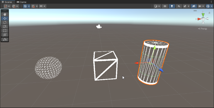
We do have a problem at this point though, and that is that we’re only displaying our front-facing triangles (as you can see very clearly in the cube and cylinder).
So let’s add the pass for the back-facing triangles to fix our first problem:
Shader "Unlit/WireframeShader"
{
    Properties
    {
        _MainTex("Texture", 2D) = "white" {}
        _WireframeFrontColour("Wireframe front colour", color) = (1.0, 1.0, 1.0, 1.0)
        _WireframeBackColour("Wireframe back colour", color) = (0.5, 0.5, 0.5, 1.0)
        _WireframeWidth("Wireframe width threshold", float) = 0.05
    }
    SubShader
    {
        Tags { "RenderType" = "Opaque" "Queue" = "Transparent"}
        LOD 100
        Blend SrcAlpha OneMinusSrcAlpha

        Pass
        {
            // Removes the front facing triangles, this enables us to create the wireframe for those behind.
            Cull Front
            CGPROGRAM
            #pragma vertex vert
            #pragma fragment frag
            #pragma geometry geom
            // make fog work
            #pragma multi_compile_fog

            #include "UnityCG.cginc"

            struct appdata
            {
                float4 vertex : POSITION;
                float2 uv : TEXCOORD0;
            };

            struct v2f
            {
                float2 uv : TEXCOORD0;
                UNITY_FOG_COORDS(1)
                float4 vertex : SV_POSITION;
            };

            // We add our barycentric variables to the geometry struct.
            struct g2f {
                float4 pos : SV_POSITION;
                float3 barycentric : TEXCOORD0;
            };

            sampler2D _MainTex;
            float4 _MainTex_ST;

            v2f vert(appdata v)
            {
                v2f o;
                o.vertex = UnityObjectToClipPos(v.vertex);
                o.uv = TRANSFORM_TEX(v.uv, _MainTex);
                UNITY_TRANSFER_FOG(o,o.vertex);
                return o;
            }

            // This applies the barycentric coordinates to each vertex in a triangle.
            [maxvertexcount(3)]
            void geom(triangle v2f IN[3], inout TriangleStream<g2f> triStream) {
                g2f o;
                o.pos = IN[0].vertex;
                o.barycentric = float3(1.0, 0.0, 0.0);
                triStream.Append(o);
                o.pos = IN[1].vertex;
                o.barycentric = float3(0.0, 1.0, 0.0);
                triStream.Append(o);
                o.pos = IN[2].vertex;
                o.barycentric = float3(0.0, 0.0, 1.0);
                triStream.Append(o);
            }

            fixed4 _WireframeBackColour;
            float _WireframeWidth;

            fixed4 frag(g2f i) : SV_Target
            {
                // Find the barycentric coordinate closest to the edge.
                float closest = min(i.barycentric.x, min(i.barycentric.y, i.barycentric.z));
                // Set alpha to 1 if within the threshold, else 0.
                float alpha = step(closest, _WireframeWidth);
                // Set to our backwards facing wireframe colour.
                return fixed4(_WireframeBackColour.r, _WireframeBackColour.g, _WireframeBackColour.b, alpha);
            }
            ENDCG
        }

        Pass
        {
            // Removes the back facing triangles.
            Cull Back
            CGPROGRAM
            #pragma vertex vert
            #pragma fragment frag
            #pragma geometry geom
            // make fog work
            #pragma multi_compile_fog

            #include "UnityCG.cginc"

            struct appdata
            {
                float4 vertex : POSITION;
                float2 uv : TEXCOORD0;
            };

            struct v2f
            {
                float2 uv : TEXCOORD0;
                UNITY_FOG_COORDS(1)
                float4 vertex : SV_POSITION;
            };

            // We add our barycentric variables to the geometry struct.
            struct g2f {
                float4 pos : SV_POSITION;
                float3 barycentric : TEXCOORD0;
            };

            sampler2D _MainTex;
            float4 _MainTex_ST;

            v2f vert(appdata v)
            {
                v2f o;
                o.vertex = UnityObjectToClipPos(v.vertex);
                o.uv = TRANSFORM_TEX(v.uv, _MainTex);
                UNITY_TRANSFER_FOG(o,o.vertex);
                return o;
            }

            // This applies the barycentric coordinates to each vertex in a triangle.
            [maxvertexcount(3)]
            void geom(triangle v2f IN[3], inout TriangleStream<g2f> triStream) {
                g2f o;
                o.pos = IN[0].vertex;
                o.barycentric = float3(1.0, 0.0, 0.0);
                triStream.Append(o);
                o.pos = IN[1].vertex;
                o.barycentric = float3(0.0, 1.0, 0.0);
                triStream.Append(o);
                o.pos = IN[2].vertex;
                o.barycentric = float3(0.0, 0.0, 1.0);
                triStream.Append(o);
            }

            fixed4 _WireframeFrontColour;
            float _WireframeWidth;

            fixed4 frag(g2f i) : SV_Target
            {
                // Find the barycentric coordinate closest to the edge.
                float closest = min(i.barycentric.x, min(i.barycentric.y, i.barycentric.z));
                // Set alpha to 1 if within the threshold, else 0.
                float alpha = step(closest, _WireframeWidth);
                // Set to our forwards facing wireframe colour.
                return fixed4(_WireframeFrontColour.r, _WireframeFrontColour.g, _WireframeFrontColour.b, alpha);
            }
            ENDCG
        }
    }
}
If you save and create a shader, you should be able to drag this onto the primitives in your scene and see that the back-facing triangles are now visible as well. (I’ve given them a red color to make it more obvious.)
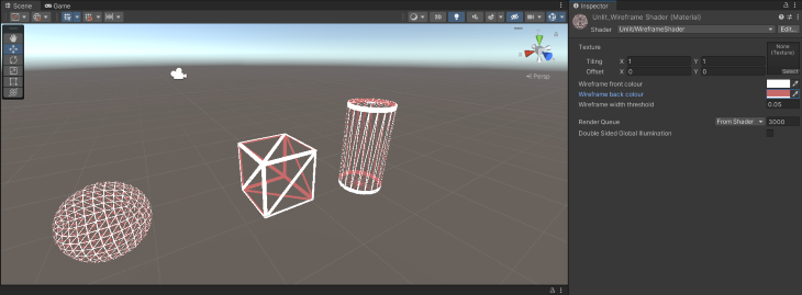
Wonderful! You’ve just created your own wireframe shader! I hope that this has been helpful to you, and I wish you well on your journey to shader wizardry. You can learn more about shader effects and nodes in this guide.
The post Building a wireframe shader with Unity and Unity Shader Graph appeared first on LogRocket Blog.
from LogRocket Blog https://ift.tt/nXRL7ht
Gain $200 in a week
via Read more


